产品描述
Characteristics
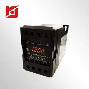
- Measurement: DC voltage
- Four-bit 0.34 "digital tube display, range automatic conversion, decimal point automatically switch according to range
- Current and voltage ratio can be set freely
- Isolation mode: power supply, input, output three-way complete isolation anti-jamming ability strong
- Output: RS485 Communication Interface MODBUS-RTU protocol, etc.
- Working principle: The internal use of microprocessor for mathematical operations, the nonlinear input signal can be extremely high precision linear correction. Lightweight, beautiful appearance, 35mm standard guide rail installation, easy loading and unloading
Overview
The Display transmitter series is a kind of DC analog signal or digital signal device which changes the power and non-power parameters in the power grid into linear. It can be connected with a microcomputer through the RS485 serial interface to form a measurement and control system. The internal use of switching power supply, the auxiliary power supply requirements are low (power supply AC, DC General), the series has a strong anti-jamming performance, its anti-jamming performance in line with IEC electromagnetic compatibility level 3 provisions, other in line with GB/t 13978-92 provisions, the series is applicable to machinery, telecommunications, electricity, petroleum, chemical, steel , Sewage treatment, building construction, power plants, substations and other modern power supply and distribution systems, a high-performance intelligent transmitter.
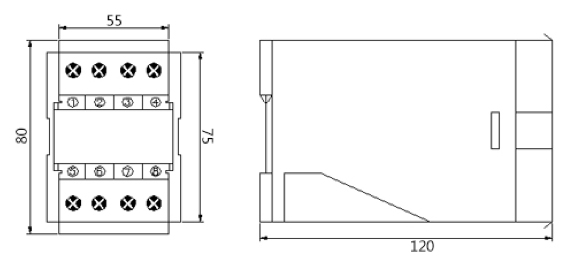
Appearance dimensions
Technical parameters
Accuracy: ≤±0.2%R.O. or ±0.5%R.O.
Linearity: ≤±0.1%R.O.
Full scale calibration: ≤20%of R.O.
0-point calibration: ≤10%of R.O.
Isolation strength: 1500Vdc (1 minutes)
Input and output are completely isolated
Working power supply: AC/DC86~265V±10 Power consumption: AC approx. 4VA,DC approx. 4W
Response time: ≤400msec.
Working environment:-10~60℃
Input: 0-30V or 0-60V
Output ripple: ≤0.2%R.O. (Peak peak)
Shell material: ABS Fireproof Material
Mounting method: 35mm Standard guide rail or base screw mounting
Dimensions: (L) x55 (W) x75 (H) mm Weight: approx. 400 g
Voltage and current parameter setting and key function
1, Alarm parameter settings: General Current/voltmeter users do not need to set data, press set greater than 3 seconds to enter the alarm mode settings menu, key shift, digital tube flashing, key modification, and then press set confirmation, down to continue to press set.
Press and hold the modifier key not to subtract, each click to modify the key to add.
2, when displaying the measured value, press the modifier key to switch to the input, output display.
3, when the user for the current input, can be directly set through the menu display range.
4, in any set state, if there is no operation within 15 seconds, it is automatically returned to the measurement display. 5, special functions, this instrument can be used as DC voltage or AC voltmeter, do not need to change the terminal, as long as you want the voltage connected to the input, set to the parameters you want can be. This feature is required to indicate when ordering.
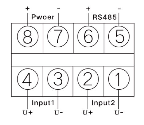
Wiring diagram Note: The wiring mode is based on the instrument brand wiring
MODBUS_RTU Communication Statute (this Agreement adopts the master and answer method)
NKB-27RX Intelligent Series Instrumentation/transmitter:
NKB-27RX Intelligent Series of instrumentation/transmitters with a new design, revolutionized the concept of traditional meters, with multi-functional, high-precision, digital, programmable, compact structure, multi-screen display characteristics, it can meet the power industry in the future demand for meters.
MODBUS Communication Protocol:
ModBus Communication protocol allows NKB-27RX Intelligent series of instrumentation/transmitters with Schneider, Siemens, AB, GE and many other internationally renowned brands of programmable sequential controllers (PLC), RTU, SCADA systems, Information exchange and data transfer between DCS or monitoring systems that are ModBus compatible with third parties.
NKB-27RX Intelligent Series Instrumentation/transmitter simply add a set of monitoring software based on a computer (or industrial control machine) (e.g., Configuration King, Intouch, FIX, Synall, etc.) can form a set of power monitoring system.
Wide range of system integration:
Series instrumentation/transmitter provides a standard RS-485/422 communication interface and ModBus communication protocol, this communication protocol has been widely used by domestic and foreign power industry and industrial control industry as the standard of system integration.
Types and formats of communication data:
The information is transmitted asynchronously and in bytes. The communication information passed between the main station and the from the station is a 11-bit word format:
| Word format (serial data) | 11-bit Binary |
| Starting bit | 1 digits |
| Data bits | 8 digits |
| Parity bit | No parity bit |
| Stop bit | 1-bit A |
- Communication data (information frame) format
| Data formats: | Address Code | Function code | Data area | Wrong school Check |
| Data length: | 1 bytes | 1 bytes | N bytes | 16-bit CRC code (redundant Loop code) |
★ Note: 1, 1 bytes consist of 8-bit binary numbers (both 8 bit).
- ModBus is a registered trademark of Modicon Company.
3、"From the machine" in this file is both NKB-27RX intelligence.
1、Communication Information Transmission Process:
When the communication command is sent by the sending device (host) to the receiving device (from the machine), the transmission command is received from the machine that meets the corresponding address code, and the information is read according to the function code and related requirements, if the CRC is checked correctly, the corresponding task is performed, and then the execution result (data) is returned to the host. The returned information includes the address code, the function code, the data after execution, and the CRC checksum code.
If the CRC checksum fails, no information is returned.
1.1 Address Code:
The address code is the first byte (8 bits) of each communication information frame, from 0 to 255. This byte indicates that the from machine where the address is set by the user will receive information sent by the host. Each machine must have a unique address code, and only the from machine that conforms to the address code can respond to the callback information. When the information is sent back from the machine, the callback data starts with their respective address codes.
Host The address code sent indicates the sender address to be sent to, while the address code returned from the machine indicates the return from the machine address. The corresponding address code indicates where the information came from.
1.2 Function code:
Is the second byte of each communication information frame transfer. The ModBus communication protocol can define a function code of 1 to 127. The NKB-27RX Intelligent Series instrumentation/transmitter uses only a portion of the function code. Sent as a host request, through the function code to tell what action should be performed from the machine. As a from-machine response, the function code returned from the machine is the same as the function code sent from the host, and indicates that the machine has responded to the host and has done the relevant action.
Table 8.1 MODBUS Partial function code
| Function code | Definition | Operation (binary) |
| 02 | Read Switch quantity input | Read all the way or multi-channel switching status input data |
| 01 | Read switch volume output | Read all the way or multiplex switch output status data |
| 03 | Read Register data | Read data from one or more registers |
| 05 | Write Switch Quantity output | Control all the way relays "fit/split" output |
| 06 | Write a single-way register | Write a set of binary data to a single register |
| 10 | Write multi-channel registers | Write multi-set binary data to multiple registers |
1.3 Data area:
The data area includes what information needs to be returned from the machine or what action to perform. This information can be data (e.g. switching input/output, analog input/output, registers, etc.), reference addresses, and so on. For example, if the host tells the value of the register return from the machine through function code 03 (including the starting address of the register to read and the length of the read register), the returned data includes the data length and data content of the register.
For different machines, the address and data information are not the same (the Communication information table should be given). NKB-27RX Intelligent Series instrumentation/transmitter using Modbus Communication protocol, host (PLC, RTU, PC, DCS, etc.) using communication commands (function code 03), you can read its data register arbitrarily (its Data information table is detailed in the appendix).
The data registers of the NKB-27RX Intelligent series instrumentation/transmitter store up to hundreds of kilowatts of electricity (e.g. current, voltage, power, 0~31 harmonic components, etc.), and are both 16-bit (2-byte) binary data, and high in front; the maximum number of registers to read at a time (the number of various types of electricity) is 50. The command format for NKB-27RX Intelligent response is from the machine address, function code, data area and CRC code. Data in the data area are two bytes and high in front (except for electrical energy).
2、Introduction to MODBUS function code
2.1 Function Code "03": Read multi-channel Register input
For example, the host wants to read 32 from the machine register data with an address of 01 and a starting address of 0000. The address and data of the From machine (NKB-27RX Smart) data register are:
Message formats sent by the host:
| Host sending | Number of bytes | The information sent | Note |
| From the machine address | 1 | 01 | Send from a machine with an address of 01 |
| Function code | 1 | 03 | Read Registers |
| Start Address | 2 | 0000 | Starting address is 0000 |
| Data length | 2 | 0001 | Read 1 Registers |
| CRC Code | 2 | 840a | CRC code calculated by host |
Message format returned from the machine (NKB-27RX Smart) Response:
| From the machine response | Number of bytes | The information returned | Note |
| From the machine address | 1 | 01 | From the 01 from the machine |
| Function code | 1 | 03 | Read Registers |
| Read the word | 1 | 02 | 1 registers for a total of 2 bytes |
| Register Data 1 | 2 | 0~9999 | Measurement values |
| CRC Code | 2 | CRC code obtained from machine calculation |
3、Error verification code (CRC checksum):
The host or the computer can use the checksum code to determine whether the received information is correct.
Due to electronic noise or some other interference, information sometimes occurs during transmission, error verification Code (CRC) can verify whether the host or from the machine in the communication data transmission process of the wrong information, the wrong data can be discarded (whether sent or received), which increases the security and efficiency of the system. The CRC (redundant Loop code) of the MODBUS Communication Protocol contains 2 bytes, that is, 16-bit binary digits. The CRC code is calculated by the sending device (host) and placed at the end of the sending information frame.
The device receiving the information (from the machine) recalculates the CRC that received the information, comparing whether the calculated CRC is consistent with the received, and if the two do not match, an error is indicated.
In the CRC calculation only 8 data bits, starting bit and stop bit, if there are parity bits also include parity bits, are not involved in CRC calculation.
- The CRC code is calculated in the same way:
- Preset a 16-bit register is hexadecimal FFFF (that is, all 1); The register is called the CRC Register;
- The low of the first 8-bit binary data (both the first byte of the communication frame) and the 16-bit CRC register8 bits different or, put the result in the CRC register;
3.Move the contents of the CRC register to the right one (low) to fill the highest position with 0, and check the removal position after the right shift;
4.If the emigration bit is 0: Repeat step 3rd (move one bit again to the right);
If the emigration bit is 1:CRC The register is different from the polynomial A001 (1010 0000 0000 0001);
- Repeat steps 3 and 4 until you move 8 times to the right, so that the entire 8-bit data is processed;
- Repeat steps 2 through 5 to process the next byte of the communication information frame;
7.When all bytes of the communication information frame are calculated according to the above steps, the 16-bit CRC registers are obtained with high and low Bytes are exchanged;
- Finally, the content of the CRC Register is: CRC code.
4、Communication error information and processing of data:
When the NKB-27RX Smart table detects an error other than a CRC code error, it must return information to the host, the highest position of the function code is 1, that is, the function code from the machine back to the host is added 128 on the basis of the function code sent by the host. The following code indicates that an unexpected error occurred.
If there is a CRC error in the information received from the host, it will be ignored by the NKB-27RX smart table.
The format of the return error code is as follows (except for the CRC code):
Address code: 1 bytes
Function code: 1 bytes (highest bit 1)
Error code: 1 bytes
CRC code: 2 bytes.
The response sends back the following error code: 81.
Illegal function code.
The received feature Code NKB-27RX Smart table is not supported. 82.
The illegal data location.
The specified data location is outside the scope of the NKB-27RX Smart table. 83.
Illegal data values.
The data value received by the host is exceeded by the data range of the NKB-27RX smart address.


用户评论
目前还末有评论