产品描述
application
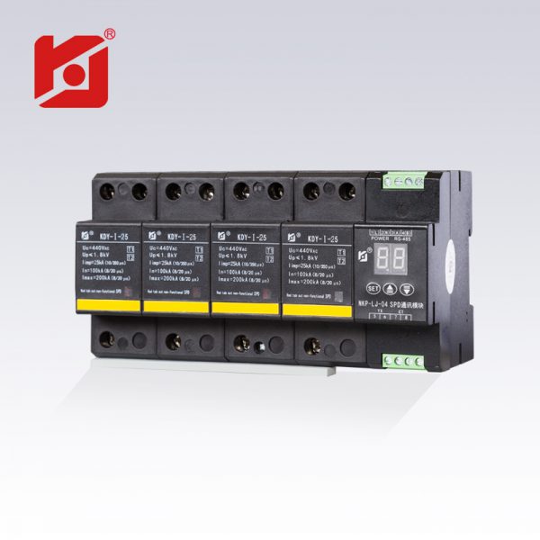
KEJIA® KDY-I-25RX power supply surge protector has a large flow capacity and is a switch-type primary power supply lightning protection device. The surge protector has no leakage current, no freewheeling, reliable performance and stable operation. According to the principle of lightning protection, once the lightning energy is released by one time, there is still a high residual voltage on the power line. It should be matched with the lightning protection device at the rear stage of the lightning protection system so that the lightning energy can be released step by step to effectively protect the terminal power supply. equipment.
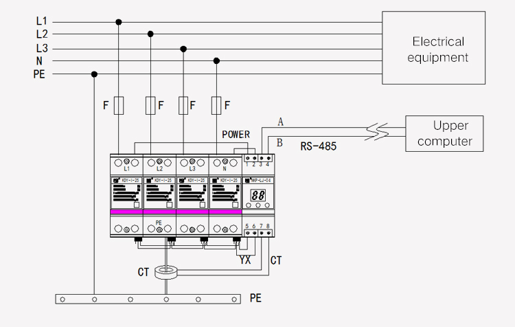
When the KEJIA® KDY-I-25RX power supply lightning protector is used, the power supply lightning protection module is partially connected between the protected end and the earth (L1, L2, L3, N line and PE) lines, and is installed on the DIN35 rail. Can be installed in the power distribution box and various standard cabinets. When the SPD communication module is partially wired, the working power terminal must be connected to the protection side of the power SPD. The sampling transformer should be connected in series in the down conductor of the SPD. The remote signaling terminal should be connected to the remote SP contact of the power SPD. Used to indicate the failure status of the power supply SPD. RS-485 serial communication terminal is connected to the remote intelligent management unit or the integrated automation system 485 bus (background host computer).
Parameters
Nominal voltage Un : 220/380V AC
Maximum continuous operating voltage Uc: 440V AC
Nominal discharge current In : 100kA (8/20μs)
Maximum discharge current Imax: 200kA (8/20μs)
Impulse discharge current Iimp: 25kA (10/350μs)
Voltage protection level Up<1800V
Front empty open or fuse F: 315A
Remote contact: 1, 3 normally closed, 2, 3 normally open
Response time: 25ns
Working temperature: -40°C to +80°C
Upper lead L/N: ≥16mm2
Lower lead PE: ≥25 mm2
Sampling method: supporting special transformers, counting when lightning current passes;
Display mode: 2 digits 0.30 inch red high-brightness LED digital tube;
Local address: hexadecimal 01H-FFH, corresponding to decimal 1-255; boot default is 01, through the button settings, can be set to be connected to the same number of lightning protector;
baud rate: 9600, 4800, 2400, 1200, 600bit / s optional, boot default 9600bit / s, through the button settings;
With RS-485 communication interface, using simplified MODBUS-RTU communication protocol to communicate with the management machine;
Maximum count: 99 times, return to 01 times when full;
Data storage: save power data, save power for up to 10 years;
Installation method: 35mm DIN rail, EN60715 standard
Dimensions
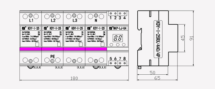 NKP-LJ-04 communication module terminal definition
1 - power supply L/+;
2 - power supply N/-;
3 - RS-485 communication output end (A);
4 - RS-485 communication output at the other end (B);
5 - power lightning protection device (YX) contact end (not polarity);
6 - power lightning protector remote (YX) contact the other end (not polarity);
7—output end of transformer (no polarity);
8 - The other end of the transformer output (no polarity).
Wiring diagram


用户评论
目前还末有评论